Ubisense Tags
Ubisense Tags are small devices that you can attach to host assets such as vehicles, goods, and tools that you want to locate and track in real time. All Ubisense Tags emit UWB pulses, which are detected and timed by UWB Sensors. This data is then used by the DIMENSION4 Real-time Location System to identify the location of the tag.
In addition, Multi-mode Tags emit narrow-band 2.4GHz transmissions. These are used by 2.4GHz Receivers to identify the GPS location of the host assets when they are out of range of the UWB Sensors.
The types of tag that are supported by the DIMENSION4 Real-time Location System are described in the following table.
| Tag | Purpose |
|
Ubisense Industrial Tag |
To identify the location of a host asset in real time. These tags can be used both indoors and outdoors. For more information, see Ubisense Industrial Tags and Multi-mode Tags. |
|
Ubisense Multi-mode Tag |
To identify the location of a host asset in larger outdoor areas where there are no UWB sensors. The GPS location is transmitted to a 2.4GHz Receiver. For more information, see Ubisense Industrial Tags and Multi-mode Tags. |
|
Ubisense Tool Tags |
To identify the location of host objects, typically a tool, in real time. The location is communicated to an external system that controls the configuration settings of the tool. For more information, see Ubisense Tool Tags. |
|
Ubisense Tag Module |
To integrate the tracking features of Ubisense tags with other devices, for example with host tools. For more information, see Ubisense Tag Module. |
Ubisense Industrial Tags and Multi-mode Tags
Ubisense Industrial Tags and Ubisense Multi-mode Tags are devices that you can use to locate your assets such as vehicles, in real-time.
Industrial Tags
Industrial Tags are mechanically strong and resistant to dust and water. You can use these tags in harsh environments such as car manufacturing units.
After you attach an Industrial tag to an asset, the asset can be located to an accuracy of up to 15 cm in either 2D or 3D, in real-time.
Industrial tags are also available with a reed switch instead of a button which makes them suitable for use in extreme weather conditions, for example, on vehicles that are driven in heavy rainfall. They are activated using a magnet.
Multi-mode Tags
Multi-mode Tags are designed for use in situations where the tag must be tracked both indoors and outdoors. Outdoors the tag is located through the use of GPS.
Ubisense 2.4GHz Receivers are needed to receive the 2.4GHz uplink transmission from the tag that contains the GPS location.
Attaching Tags
You can securely attach the tags to your host assets, by using a variety of attachment options, depending on:
- The type of host asset on which you are mounting the tag.
- The environment in which the tags are likely to be used.
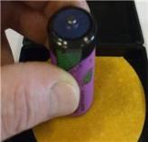
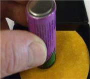
Features of Industrial Tags and Multi-mode Tags
The features of Industrial Tags and Multi-mode Tags, are shown in the following figure.
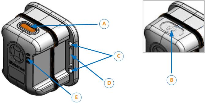
Features of Industrial Tags and Multi-mode Tags
The gasket is black on an Industrial Tag (as shown above) and blue on a Multi-mode Tag.
| Feature | Description |
|---|---|
|
A. Button |
The button enables you to activate the tag from the deep sleep state. |
|
B. Magnet Point (Industrial Tag only) |
Instead of a button, an Industrial Tag can be supplied with a magnetic reed switch. To activate a tag of this type, hold the magnet against the magnet point. The correct position may depend on the strength and polarity of the magnet being used to activate the tag.
|
|
C. Mounting holes |
The tag has four mounting holes. The diameter of each hole is 4.3 mm. You can connect the tag to either a universal mounting bracket, or a custom mounting bracket. |

|
D. Strapping slots |
You can also mount the tag by using straps. The strapping apertures have the following dimensions:
|
|
E. LEDs |
The tag has three LEDs, which flash when the tag is active. The Green LED flashes to indicate that the tag is operating correctly, and the tag is communicating with the DIMENSION4 Real-time Location System. |
Additional features of the Multi-mode Tag
The Multi-mode Tag incorporates a SiRFStar-based GPS receiver.
Activating Industrial Tags and Multi-mode Tags
To ensure that the tags do not use batteries unnecessarily, Industrial Tags and Multi-mode Tags are supplied in the deep sleep (deactivated) state.
Before you use a tag for the first time, it must be woken up (activated) from the deep sleep state.
To activate a tag:
-
Do one of the following:
-
Industrial Tags and Multi-mode Tags: Press and hold the button on the tag.
-
Buttonless Industrial Tags: Hold the supplied magnet against the magnet point on the tag case.
The three LEDs light up and remain brightly lit for as long as you press the button.
-
-
Do one of the following:
-
Industrial Tags and Multi-mode Tags: Release the button.
-
Buttonless Industrial Tags: Remove the magnet from the magnet point.
The green LED blinks brightly and then starts to blink at a lower intensity, at regular intervals. The tag is now activated and ready to be used.
-
Putting an Industrial Tag or Multi-mode Tag into Deep Sleep
If an Industrial Tag or Multi-mode Tag is activated, you can put it back into the deep sleep state, to preserve battery.
It is not possible to accidentally put a tag into deep sleep because the tag sets a 'challenge' and expects a 'response'. The LED will blink one or more times and you respond by pressing the button or swiping the magnet on the tag the same number of times. The tag then repeats the challenge and you respond again. After the second challenge and a successful response, the LED blinks brighter than normal and then switches off indicating the tag is now in deep sleep.
Putting a Tag into a Deep Sleep
To put a tag into the deep sleep state:
-
Hold down the button on the tag or hold the magnet against the magnet point.
You may need to offset the magnet against the magnet point (see Features of Industrial Tags and Multi-mode Tags). - The LED first stops blinking in readiness for the first challenge. It then starts blinking again.
- Count the number of times the LED blinks brightly. This can be from one to five blinks.
- Press the button on the tag or swipe the magnet against the magnet point the same number of times.
- Carry out the second challenge:
- Count the number of times the LED blinks brightly.
- Press the button on the tag or swipe the magnet the same number of times.
-
If you are successful, the LED blinks brightly and switches off. The tag is now deactivated.
If you are unsuccessful, the green LED on the tag will continue to blink at a lower intensity, at the programmed UWB beacon rate.
Testing Whether a Tag is in Deep Sleep
You can check whether an Industrial Tag or a Multi-mode Tag is in a deep sleep by, pressing the button on the tag, or holding the magnet against the magnet point, for a few seconds.
Do not hold for too long as you will activate the tag again.
If the tag is in a deep sleep state, all three LEDs will come on and go off. However, if the green LED stops blinking briefly then the tag is still active.
Mounting Industrial Tags and Multi-mode Tags
You can mount Ubisense Industrial Tags and Multi-mode Tags by using the following options:
-
Screw and strap loop mounting.
-
Adhesive foam and Industrial Velcro® mounting.
-
Magnetic mounting.
The exploded view of a tag is shown in the following figure.
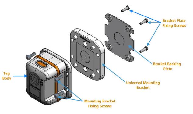
Parts of an Industrial Tag or Multi-mode Tag
| Part | Description |
|---|---|
|
Bracket backing plate |
Part of the mounting bracket. |
|
Bracket plate fixing screws |
Four M3 x 10 mm Plas-Fix® screws that are used for attaching the bracket plate to the universal mounting bracket. |
|
Mounting bracket fixing screws |
Four M4 x 10 mm A2 stainless steel screws that are used for attaching the mounting bracket to the tag. |
|
Tag body |
The body of the tag that contains the battery and the module. |
|
Universal mounting bracket |
The bracket that is used for attaching the tag to a host asset. |
Mounting Process
The process for mounting Industrial Tags and Multi-mode Tags is shown in the following figure.

Process for Mounting Industrial Tags and Multi-mode Tags
Choosing a Mounting Option
Before you fix an Industrial Tag or Multi-mode Tag to a host asset, choose the appropriate mounting option depending on the type of host asset and the environment in which the tag will be used.
You can use one of the following mounting options:
-
Screws.
-
Velcro® mounting.
-
Magnetic mounting.
-
Customized mounting options.
Mounting a Tag by Using Screws
If you want to fix the tag to a host asset by using screws:
-
Fix the bracket to the tag, as described in Fixing a Bracket to an Industrial Tag or Multi-mode Tag.
-
Fix the tag to the host asset, as described in Fixing a Tag to a Host Asset.
Velcro® Mounting
Depending on the surface properties of a host asset, you can fix the tag mounting bracket to the host asset by using either:
-
A strong adhesive foam label.
-
Adhesive Velcro® attached to the bracket backing plate.
If you require help with producing a suitable die cutter, contact Ubisense for a template of the outline of the mounting backing plate. The template is supplied as a DXF file.
The dimensions of the bracket backing plate are shown in the following figure. The measurements are in millimeters (mm).

Dimensions of Bracket Backing Plate
Magnetic Mounting
The universal mounting bracket contains a space for a 20 x 5 mm circular magnet, as shown in the following figure.
![]()
Space for Magnet
To fix a tag to a host asset by using a magnet:
-
Insert the magnet into the space in the universal mounting bracket.
-
By using the four M3 x 10mm Plas-Fix® screws, fix the backing plate together with the mounting bracket. After the backing plate is connected to the mounting bracket, this provides a flat surface.
-
Attach a protective pad to the underside of the bracket using the die cutter outline, described in Velcro® Mounting.
We recommend that you use a magnet with the specifications listed in the following table.
| Diameter | 20 mm |
| Height | 5 mm |
| Coating |
N42 – Ni-Cu-Ni plated |
| Pull |
Typical 6.4 kg |
Customized Mounting Options
To provide application-specific mounting of tag, you can customize the mounting bracket.
For example, you can create a custom mounting bracket for auto manufacturing applications by bonding or bolting a PTFE riser or rubber mount to the universal mounting bracket, as shown in the following figure.
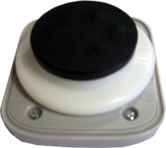
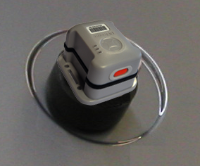
Custom Magnetic Mounting on a Vehicle
Do not use these mounting options to attach a tag to:
- Vehicles that are driven on public highways.
- Vehicles that might travel at a high speed.
Fixing a Bracket to an Industrial Tag or Multi-mode Tag
After choosing a mounting option, fix either of the following brackets to an Industrial Tag or Multi-mode Tag:
-
Universal mounting bracket supplied by Ubisense.
-
Custom mounting bracket.
When fixing a bracket, depending on the environment in which the tag will be used, you can also use neoprene or silicon gaskets to form a watertight seal.
About Using Neoprene or Silicon Gaskets
If your industrial environment is harsh, to form a complete watertight seal, you can fit neoprene or silicone gaskets between:
-
The tag and the universal mounting bracket.
-
The mounting bracket and host asset.
The tag and bracket include a recess (space) where you can fit the gasket, as shown in the following figures.
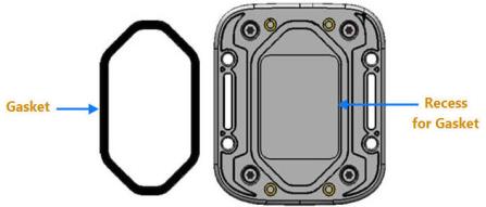
Recess for a Tag Gasket
Recess for a Bracket Gasket
Ensure that you choose an appropriate sealing material based on its temperature and media resistance. For information about various rubber characteristics, see: http://www.rubbermanuk.co.uk/rubber_propertys.htm.
Fixing a Universal Mounting Bracket
You can fix a universal mounting bracket to a tag by using either:
-
The four M4 x 10 mm A2 stainless steel screws that are supplied with the mounting bracket.
-
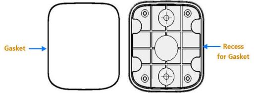
Straps. The tag has strap apertures that are 19.5 mm long and 4 mm wide.
If you are mounting a tag by using straps, we recommend that you use extruded polyester straps up to 19 mm wide.
The dimensions of the screw and strap mounting holes on an Industrial Tag or Multi-mode Tag, are shown in the following figure.
Dimensions of Screw and Strap Mounting Holes
Fixing a Custom Bracket
To fix a custom bracket to a tag, connect the bracket directly to the tag, by using the four screw holes provided on the base of the tag, shown in the following figure.
![]()
Tag Screw Fixing Holes
The screw holes have the following dimensions:
-
Diameter: 2.4 mm
-
Depth: 6 mm
To ensure that the tag is held firmly in place, we recommend that you use self-tapping plastic screws:
-
Diameter: 3 mm
-
Length: 5.5 mm
Fixing a Tag to a Host Asset
When fixing a tag to a host asset, you can optionally place a gasket between the bracket base and the host asset to create a watertight seal. For more information, see About Using Neoprene or Silicon Gaskets.
If you fix a tag by using Adhesive foam, Velcro, or a Magnet, place the tag directly on the host asset.
To fix a tag to a host asset by using screws, use the M4 Cap Head screws supplied with the bracket. The screw holes on the bracket are shown in the following figure.
![]()
Top View of Universal Mounting Bracket Screw Fixing Holes
Ubisense Tool Tags
Ubisense Tool Tags are small, sturdy devices that you can attach to tools such as torque wrenches.
When you attach a Tool Tag to a tool, depending on your system configuration and environment, you can locate the tool to an accuracy of 15 cm in 3D in real-time. You can use Tool Tags in different types of environments, including industrial sites.
Types of Tool Tags
Ubisense provides the following types of tool tag:
-
Head and Battery Unit Tool Tag: The Battery Unit is connected to the Head Unit by using a micro‑USB B power cable.
-
Integrated Tool Tag: The Battery Unit and Head Unit are combined into a strong casing.
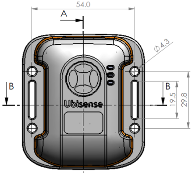
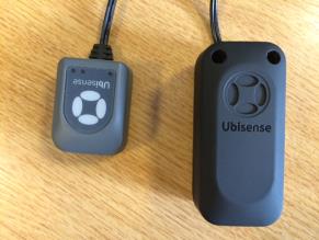
Features of Tool Tags
The features of the Integrated Tool Tag and Head and Battery Unit Tool Tag, are shown in the following figure.
Features of Tool Tags
| Feature | Description |
|---|---|
|
A. Power LED (yellow) |
Indicates that the tag is receiving power and is communicating with the DIMENSION4 Real-time Location System. |
|
B. Programmable LEDs (green and red) |
By default, these LEDs are not used. |
|
C. Strapping Slots |
You can mount a Battery Unit or an Integrated Tool Tag by using straps. The strap apertures have the following dimensions:
|
|
D. Power Cord Connector |
The Battery Unit and Integrated Tool Tag have a mini USB power cord connector on the top. This cord connector is used for transferring power to the Head Unit. |
|
E. Philips Head Screws |
Screws that connect the body of the tag to its front case. |
Head and Battery Unit Tool Tag: Power Supply Options
Depending on your requirements, you can use various power supply options to power-up the Head Unit. The power supply option that you use also determines how you prepare and use the tag, as described in the following table.
| Power Supply Option | How to Use the Tag... |
|---|---|
|
Plug the tag into a micro USB supply port. |
The Head Unit has a long cable length. Fold the cable neatly and clamp the tie-wrap to the tool. You can discard the Battery Unit. |
|
Plug the tag into a power supply, by using a screw terminal block. |
Cut the cable to the required length, and prepare the wire ends, as described in Preparing a Head and Battery Unit Tool Tag. Connect the wire ends into the screw terminal block. You can discard the micro USB plug and the Battery Unit. |
|
Use the Battery Unit. |
Use the tag as described in The Head and Battery Unit Tool Tag is supplied with a standard cable (wire) length, as shown in the following figure. . |
|
Up to three Head Units, powered from a single power source. |
Cut the cables from each Head Unit and prepare them, as described in The Head and Battery Unit Tool Tag is supplied with a standard cable (wire) length, as shown in the following figure. . We recommend that you solder the wires together. If you do not want to solder the wires together, you can either:
|
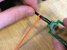
Preparing a Head and Battery Unit Tool Tag
The Head and Battery Unit Tool Tag is supplied with a standard cable (wire) length, as shown in the following figure.
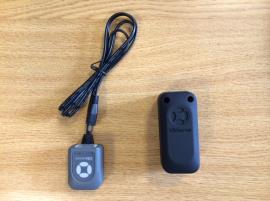
Head and Battery Unit Tool Tag
Before you attach a Head and Battery Unit Tool Tag to a tool, you must cut the wire to the correct length, depending on your particular requirements.
To prepare the tag, cut the wire to the appropriate length:
-
Determine the required length of the wire. Ensure that you allow sufficient length to properly terminate and strain-relieve the wires. Cut the wire to the appropriate length, as shown in the following figure. Discard the plug.
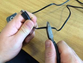
Cutting the Wire to the Required Length
-
Strip the wires and twist the individual strands together as shown in the following figures.
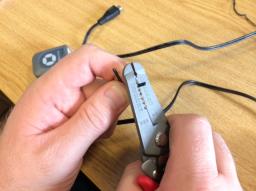
Stripping the Wires
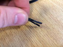
Prepared Wires
-
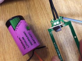
Remove the battery holder PCBA from the Battery Unit. Remove the battery, and locate the wire entry slot, shown in the following figure.
Battery Unit with the
Battery and Holder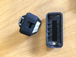
Battery Unit without the
Battery -
Pass the wire through the wire-entry slot, as shown in the following figure.
Passing the Wire through the Wire-entry Slot
-
Connect the wires to the terminal block on the battery holder as shown in the following figure.
Connecting the Wires
Ensure that you use the correct polarity. The positive terminal is marked on the Printed Circuit Board with a + symbol. The wire with the White Stripe is the positive wire.
-
Install the strain relief cable tie on the cable as shown in the following figure.
Installing the Strain Relief
To provide strain relief, pull the cable tie tight. Cut the excess length of the cable tie. -
Install the battery holder back in the battery box, ensuring that the strain relief is placed as shown in the following figure.

Battery Holder Installed in the Box
-
Reinstall the battery and assemble the Battery Unit, as shown in the following figure.
Assembled Head and Battery Unit
The yellow LED on the Head Unit slowly increase in brightness. After a few seconds, the yellow LED starts flashing to indicate the tag is communicating with the DIMENSION4 Real-time Location System.
You can now use the Tool Tag.
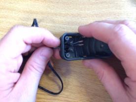
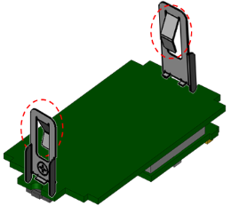
Activating an Integrated Tool Tag
The Integrated Tool Tag includes a battery. To reduce the loss of battery life, the tag is supplied in the deep sleep (deactivated state).
To activate the tag:
-
Separate the body of the tag from the front cover by unscrewing the four screws on the front case of the tag, shown in the following figure.
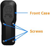
Front Case of the Integrated Tool Tag
-
Connect the Head Unit of the tag to the twenty-way pin connector on the printed circuit board of the tag, as shown in the following figure.

Activating an Integrated Tool Tag
The yellow LED on the head unit slowly increases in brightness, indicating that the tag has been activated. After a few seconds the LED starts flashing to indicate that it is communicating with the DIMENSION4 Real-time Location System.
- Replace the front case of the tag by connecting the four screws.
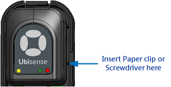
Checking that a Tool Tag is Activated
To check that a Tool Tag has been activated, insert a paper clip or wire on the side of the unit for less than 3 seconds.
If the LED is constantly lit when you press the button, the tag is still in the deep sleep (deactivated) state.
If you want to activate the tag, repeat the procedure, pressing the button for more than 3 seconds.
Putting a Tool Tag into Deep Sleep
If a Tool Tag is activated, you can put it back into the deep sleep state at any time, to preserve battery.
To access the button inside the tag, you require a paper clip or a screwdriver.
-
Insert and hold a paper clip or screwdriver into the slot on the side of the tag, shown in the following figure.
- The LED first stops blinking in readiness for the first challenge. It then starts blinking again.
- Count the number of times the LED blinks brightly. This can be from one to five blinks.
- Using the paper clip or screwdriver, press the button on the tag the same number of times.
- Carry out the second challenge:
- Count the number of times the LED blinks brightly.
- Using the paper clip or screwdriver, press the button on the tag the same number of times.
-
If you are successful, the LED blinks brightly and switches off. The tag is now deactivated.
If you are unsuccessful, the green LED on the tag will continue to blink at a lower intensity, at the programmed UWB beacon rate.
The tag is deactivated.
Ubisense Tag Module
The Ubisense Tag Module is a wireless module that you can directly integrate with other devices for the real-time location of objects within a building. For example, you can integrate the Tag Module functionality to your own custom device, so that you can fix it to your tools.
For important information about the regulatory information related to integrating the Tag Module with other devices, see System Validation and Integrity.
The Tag Module transmits UWB pulses. The sensors installed in the building detect these pulses and locate the 3D position of the tag. When compared to other wireless technologies, UWB technology is less affected by multipath interference. Therefore, the position of the tag can be found with greater accuracy.
You can use Tag Modules in different types of environments including healthcare, workplace productivity, security, retail management and manufacturing.
Integrating a Tag Module
The Tag Module includes a Printed Circuit Board (PCB), with the following components:
-
All required antennas, which are permanently attached to the module.
-
A 20-way expansion header that can be used to supply power to the device. The header also allows the module to have two-way communication with a host device or external sensors and actuators.
When integrating the Tag Module with another device, ensure that the antennas are not obstructed by tall components, shielding, or mounting screws.
To ensure that the antennas do not get detuned, retain an air gap of at least 1 mm around both antennas.
While you can use the connector to fix the Tag Module, we recommend that you fix the module to a PCB securely by fitting the supplied double-sided pad to the top of the screening can.
For more information about the mechanical and electrical interfaces of the Tag Module, and information about integrating the Tag Module into a custom hardware platform, see the Tag Module Integration Guide.
Dimensions
The dimensions of the module PCB are shown in the following figure.
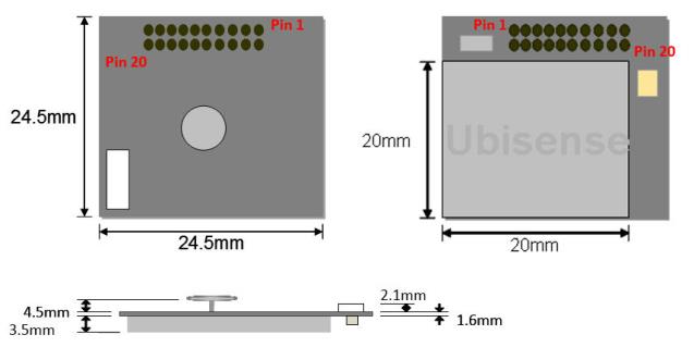
Dimensions of the Tag Module
Power Requirements
Power should be supplied to the following pins on the header:
-
Pin 3: 2.3V – 5.25V DC power input.
-
Pins 5, 6, 9, 10, 14, 18, 19: Ground.
Header and Connector Specifications
You can use a number of pins on the module header for:
-
Digital input and output.
-
Analogue input.
The header used on the module is Major League TSHS-5 10-D-04-A-F-LF, which a standard 1.27 mm pitch through-hole pin header.
The recommended connector to use with the module is Connector: Major League LSSHS-5 10-D-06-F-TB-P-LF (SMD). For more information and ordering details, see the Major League Electronics website, at: http://www.melectronics.com/products/.
System Validation and Integrity
The Tag Module is supplied with integration instructions you can follow, to ensure that the tag element of the design meets US and EU regulatory requirements.
However, the regulatory compliance of the Tag Module is likely to change in the scenarios listed in the following table.
| Scenario | Description |
|---|---|
|
Modifications to the Tag Module |
If you modify the supplied Tag Module, it might become non‑conformant with performance or regulatory specifications. In such situations, it is your responsibility to ensure the regulatory compliance of the Tag Module. |
|
Integration of the Tag Module to other equipment beyond the tag circuit. |
The integration partner must ensure the regulatory compliance of elements of equipment into which the tag is integrated beyond the tag circuit itself. Ubisense does not take responsibility for the performance or regulatory conformance of those elements of the design. |
|
OEM applications |
The end manufacturer must ensure that their final product continues to meet all relevant approvals and (if applicable) EU Directives. Ubisense will not accept liability for any subsequent non-conformations in this scenario. |
Replacing and Disposing of Batteries
This chapter explains how to replace and dispose of batteries, of the following tags:
-
Tool Tags.
-
Industrial Tags.
-
Multi-mode Tags.
The tag parameters are retained when the power source is removed from the tag.
Replacing the Battery of a Tool Tag
Tool Tags are supplied with a connectorized A-size 3.6 V battery (Part number: TOOLBAT). Tool Tags regularly report their battery status to the DIMENSION4 Real-time Location System through the UWB Sensors.
To replace the battery in a Tool Tag (Battery Unit or an Integrated Tool Tag):
-
Remove the screws on the front cover of the tag.
-
Do one of the following:
- Battery Unit: Remove the old battery, and then insert a new battery.
- Integrated Tool Tag: Remove the old battery by unplugging the battery connector. Insert a new battery, and then plug the connecter into the battery socket, as shown in the following figure.
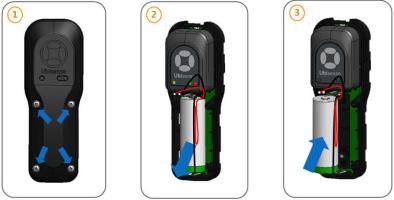
Replacing Battery of an Integrated Tool Tag
-
Replace the front cover of the tag by fixing the screws. The yellow LED on the tag gradually lights up to indicate that it is working correctly. The DIMENSION4 Real-time Location System can then find the location of the tag.
If the LED does not flash after you have replaced its battery, remove the battery and then reinsert the battery. Wait for 30 seconds.
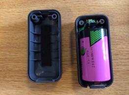
Replacing the Battery of Industrial Tags and Multi-mode Tags
This procedure explains how to replace the batteries of Ubisense Industrial Tags and Multi-mode Tags.
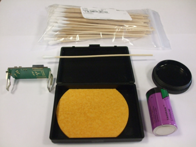
Prerequisites
Before you begin, ensure that you have the following tools and components:
-
M3 Torx variable torque screwdriver (manual or electric), set to a torque of 0.8 Nm.
-
Tadiran™ TL-2770 3.6 V Size-C (8.5Ah) Lithium Thionyl Chloride batteries. More information about Tadiran batteries is available at: http://www.tadiranbatteries.de/pdf/lithium-thionyl-chloride-batteries/SL-2770.pdf.
-
Electrolube™ SOB01K contact treatment Oil 2X.
-
A Metcal AC-YS4 Sponge.
-
AF-SBU000 safebuds.
Precautions
When replacing the battery of an Industrial Tag or Multi-mode Tag, ensure that you:
-
Take anti-static precautions for dismantling and reassembling tag.
-
Follow the Health and Safety (H&S) procedures and use appropriate protection, for example, wear eye protection and gloves.
When replacing the battery, do not separate the case lid (with the barcode label) and the Tag Module. If you do this, the module's programmed Tag ID will no longer be associated with the Tag ID on the barcode label.
Process
The process for replacing the battery of an Industrial Tag or Multi-mode Tag, is shown in the following figure.

Battery Replacement Process
You can replace the battery either with:
-
An individual operator performing all the steps.
-
A number of operators, each performing particular tasks described in the process.
Dismantling the Industrial Tag or Multi-mode Tag
To dismantle an Industrial Tag or Multi-mode Tag:
-
Place the tag upside down. You should be able to see the large Ubisense CE label.
-
By using an electric screwdriver, remove the four M3 x 10 mm screws. To prevent plastic swarf contamination, dispose of the old screws. You require new M3 x 10 mm stainless steel screws to reassemble the tag.
-
Carefully remove the top molding and place in a tray. When you remove the molding, you can see the module and carrier board.
-
Lift the carrier board and the old battery out of the base. Ensure that the gasket remains in place on the base molding.
-
Turn the base and top cases upside down to ensure any loose material falls out. Ensure that the gasket is placed properly when inverting the base molding.
-
Apply treatment oil to the carrier board and new battery, as described in Applying Treatment Oil to the Battery Carrier Contacts.
Applying Treatment Oil to the Battery Carrier Contacts
To prevent fretting of the battery contacts and the battery terminals, apply treatment oil to the battery carrier contacts.
We recommend that you purchase SOB01K Contact Treatment Oil 2X from Electrolube (Farnell part code 315-336). For more information about the SOB Electrolube 2X Oil, see the Technical Data Sheet available at: http://www.ulbrich-group.com/chemical-technical-products/TDS_ELECTROLUBE_SOB_2X_Contact_Treatment_Oil_eng.pdf.
This treatment oil is suitable for situations where a thin film of oil is required. You can also use the treatment oil to clean and remove any oil, grease, and dirt deposits from the contact surfaces.
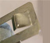
Precaution: Apply Treatment Oil Only to Metal Contacts
Ensure that you apply the treatment oil to the area of the battery contact (the outside of the angled surface of the sprung clip portion) that touches the battery, shown in the following figure.
Angled Surfaces that Touch the Battery
Ensure that you apply the treatment oil only to the metal contacts. The treatment oil might have adverse effects on some paints, rubbers, and thermoplastics, including ABS/PC blends, such as those used for the enclosure.
The supplier describes various ways in which you can apply the treatment oil. However, because of the design of the battery contacts and the small area to which you must apply the treatment oil, we recommend that you use a safe bud (cotton bud), shown in the following figure.
Using a Safe Bud to Apply Treatment Oil
To apply the treatment oil:
-
Select a clean, dry area to work.
-
The Electrolube SOB01K treatment oil removes any small deposits from the battery contacts. However, if there is any hardened dirt or tarnish on the battery contacts, clean the contacts with a suitable material such as canvas, leather, cloth, hard wood, or abrasive that can absorb the oil.
-
Wet the safe bud with a small amount of the Electrolube SOB01K contact treatment oil 2X.
-
Apply the oil to both contacts in a circular motion to ensure a uniform, thin coverage.
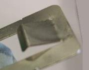
The following figures show examples for applying the treatment oil correctly.
|
|
|
|
Correct Application of Treatment Oil |
Too Much Treatment Oil Applied |
Applying Treatment Oil to the Battery Terminals
To prepare the battery terminals:
-
Moisten a rectangular piece of sponge with Electrolube Contact Treatment Oil 2X. If you place a piece of paper on the moistened sponge, the paper should get slightly dampened:
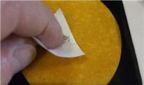
Appropriate Quantity of Oil to Apply on Sponge
-
Place the negative terminal of the battery on the sponge. To apply a thin layer of treatment oil, move the battery on the sponge in a circular motion several times:
Apply slight pressure when moving the battery. Repeat this process by placing the positive terminal on the sponge.
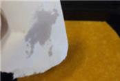
Ensure that you do not apply too much treatment oil. The following figures show examples for applying the treatment oil correctly.


Correct Application
Too Much Treatment Oil Applied
- Leave the battery to dry for 10 minutes.
Reassembling the Tag
To reassemble the tag:
- Discharge the capacitors on the carrier (module), to ensure that the tag does not receive power through the retained charge from the on-board capacitors. With the battery removed, press the button on the carrier board for at least 5 seconds. This ensures the Energy Counter based RAM variables are cleared.
-
Fit a new battery and PCB.
-
Check that the gasket is clean and undamaged.
It is very important to remove any dust or dirt on the gasket, particularly in the groove on both sides of the gasket and around the screw holes, as this may compromise the IP rating of the tag. A good way of removing the static that attracts the dust is to blow on the gasket and the tag.
-
Check that the gasket on the base molding is fitted correctly and adjust the fitting if necessary.
-
Fit the new battery into the carrier, ensuring the battery contacts are centralized at both ends.
-
-
Fit the module to the PCB, ensuring that the antenna and the top molding sealing edges are not damaged. Also ensure that the top molding with the bar code (Tag ID) is connected with the associated programmed module.
-
Place the carrier (with new battery) into the base molding.
When placing the carrier, use the wooden end of a safe bud to apply a small force to the spring clip of the battery carrier.
-
Fix the case together using four new stainless steel M3 x 10 mm Torx screws:

-
Tighten the screws using an electric torque screwdriver, set to 0.8 Nm.
-
As a final check, re-tighten the screws with a manual torque screwdriver, set to 0.8 Nm.
-
We recommend that you perform regular checks, especially on a variable torque screwdriver, to ensure that you are using the correct torque setting.
Resetting the Battery History
After you have replaced the battery in a DIMENSION4 tag, you must reset the battery history of the tag. This enables you to:
-
Clear all previous battery usage history.
-
Restart the battery history data collection process for the new battery.
You can reset the battery history:
- In the Smart Factory Offline web client, on the Tags page.
-
By using the command-line tool ubisense_battery_monitor_config, specifying the parameter battery_changed <tag ID>.
Where <tag ID> is the lower 32 bits of the 64-bit DIMENSION4 tag ID, entered in decimal format, such as 0-0-0-255.
Disposing of Batteries
After you have replaced batteries, dispose of the old batteries according to the manufacturer’s instructions, available at: http://www.tadiranbat.com/index.php/shipping-and-information.